In Part 1 of this blog, I discussed how my decision to replace my ageing home lab/server/workstation led me to adopt Proxmox. I ended the blog with a summary of the new machine’s network setup. In Part 2 of this blog, I will delve into the network configuration of the new machine. In particular, I will discuss Linux bridges, the virtual interfaces that provide network connectivity between guests and to the outside world, and how I assign dynamic IPs to guest machines without using Proxmox’s DHCP feature.
The Linux Bridges
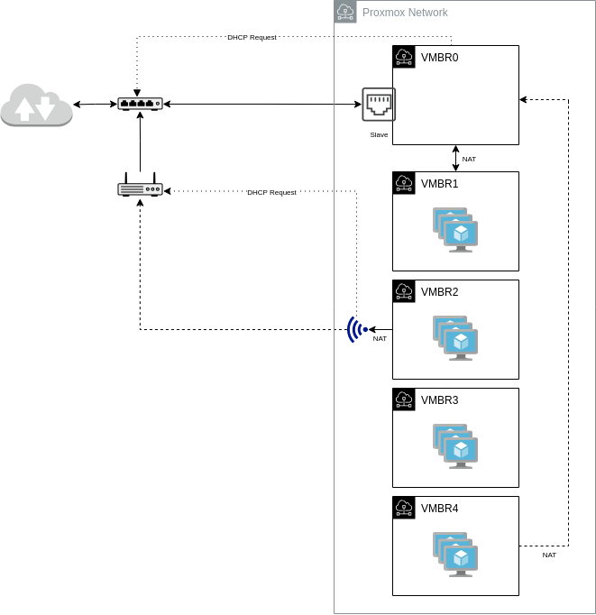
As I mentioned in Part 1, the new machine includes a Wi-Fi adapter designated for ingress and an Ethernet adapter for egress. The Linux bridges created that will use these adapters are summarised in the diagram below.
Proxmox uses ifupdown2 as its network manager, so the network configurations are stored in /etc/network/interfaces. This file can be edited directly or modified through the Proxmox GUI.
VMBR0
The VMBR0 is the Linux bridge that enslaves the Ethernet adapter and is responsible for obtaining the machine’s public IP from the ISP via DHCP. This bridge enslaves the Ethernet adapter via the bridge-ports directive, and the IP address is obtained via DHCP, hence the dhcp method in the configuration file. The Ethernet adapter is not automatically brought up; therefore, it is set to manual.
Since the bridge IP is obtained from the ISP, it will only have one (1) IP address, and it will be dynamic (assuming you are just a home broadband user), so no guest VM will use this bridge directly.
Below is the complete VMBR0 and Ethernet adapter configuration:
allow-mgmt enp10s0
iface enp10s0 inet manual
#       Ethernet network interface.

auto vmbr0
allow-mgmt vmbr0
iface vmbr0 inet dhcp
#       Main internet gateway. ISP provided IP Address via DHCP.
        bridge-ports enp10s0
        bridge-stp off
        bridge-fd 0

        post-up   echo 1 > /proc/sys/net/ipv4/ip_forward
The allow-mgmt method on each interface ensures the interface is brought up before any other. It is necessary that these interfaces be the first to go up because they are referenced later in other bridges.
The post-up command in this bridge configuration enables IP forwarding on the nodes’ network.
VMBR1
This Linux bridge is designated for virtual machines that expect ingress traffic from the internet. Incoming traffic is forwarded from the Ethernet adapter to this bridge via IP Tables port forwarding; therefore, the virtual machines created under this subnet will have static IP addresses. As of this writing, three (3) ports are open, namely: 80 (HTTP), 443 (HTTPS), and 25 (SMTP). Ports 80 and 443 are served by Nginx, which acts as a proxy for this website and file hosting service. Port 25 is served by Postfix, the MTA for my mail server.
Below is the complete VMBR1 bridge configuration.
auto vmbr1
iface vmbr1 inet static
#       External services. Fix IP. Gateway via vmbr0.
        address 192.168.1.1/24
        bridge-ports none
        bridge-stp off
        bridge-fd 0

        post-up iptables -t nat -A PREROUTING -i vmbr0 -p tcp --dport 25  -j DNAT --to-destination 192.168.1.2:25
        post-up iptables -t nat -A PREROUTING -i vmbr0 -p tcp --dport 80  -j DNAT --to-destination 192.168.1.3:80
        post-up iptables -t nat -A PREROUTING -i vmbr0 -p tcp --dport 443 -j DNAT --to-destination 192.168.1.3:443
        post-up iptables -t nat -A POSTROUTING -s '192.168.1.0/24' -o vmbr0 -j MASQUERADE

        post-down iptables -t nat -D PREROUTING -i vmbr0 -p tcp --dport 25  -j DNAT --to-destination 192.168.1.2:25
        post-down iptables -t nat -D PREROUTING -i vmbr0 -p tcp --dport 80  -j DNAT --to-destination 192.168.1.3:80
        post-down iptables -t nat -D PREROUTING -i vmbr0 -p tcp --dport 443 -j DNAT --to-destination 192.168.1.3:443
        post-down iptables -t nat -D POSTROUTING -s '192.168.1.0/24' -o vmbr0 -j MASQUERADE

        post-up   ip route add 192.168.1.0/24 dev vmbr1 src 192.168.1.1 table wifi
        post-down ip route del 192.168.1.0/24 dev vmbr1 src 192.168.1.1 table wifi
The post-up (and its corresponding post-down) command sets up the port-forwarding rule of each opened port. There is also a post-up (and post-down) that adds (or deletes) an entry in the custom routing table used for WiFi traffic. Refer to VMBR2 for details on why this configuration exists.
VMBR2
This Linux bridge is intended for guests that require only egress traffic, such as my workstation. Outgoing traffic is forwarded to the Wi-Fi adapter. This is accomplished by creating a POSTROUTING NAT rule, a custom routing table named wifi, and a custom routing rule that points to it.
post-up   iptables -t nat -A POSTROUTING -s '192.168.2.0/24' -o wlp11s0 -j MASQUERADE
   :
post-up   ip rule add from 192.168.2.0/24 table wifi
post-up   ip rule add to   192.168.2.0/24 table wifi
For guests in this subnet to reach other guests in other subnets, we need to add a routing entry in this custom table that points to the gateway of the target subnet. You can see this in the VMBR1 configuration, where a post-up command adds the VMBR1 CIDR and gateway to the Wi-Fi route table. So this would allow my workstation to access VMs on this bridge.
A Wi-Fi adapter cannot be enslaved by a bridge, unlike an Ethernet adapter, so it will issue a DHCP request for an IP address to the Wi-Fi router independently of the bridge. The IP address will be dynamic, and since it will be the default gateway in the Wi-Fi routing table, we need to update the table whenever it changes. This is accomplished by using DHCP exit hooks, implemented as scripts in the /etc/dhcp/dhclient-exit-hooks directory, which are executed whenever a DHCP event occurs.
Below is a snippet of this DHCP exit hook script:
echo "${reason}" >> $LOGFILE

case ${interface} in
     wlp11s0)
        case ${reason} in
           BOUND)
                ip route add default via ${new_routers} dev ${interface} table wifi | tee -a "$LOGFILE"
                ip rule add from ${new_ip_address}/32 table wifi | tee -a "$LOGFILE"
                ip rule add to   ${new_ip_address}/32 table wifi | tee -a "$LOGFILE"
In the script, whenever a new IP is leased (BOUND), the custom table is updated to set the new IP as the default gateway. In addition, a custom rule is added to ensure that incoming and outgoing traffic destined for this IP uses the custom table.
The complete VMBR2 bridge configuration is shown below:
auto wlp11s0
iface wlp11s0 inet dhcp
#       Wifi network interface.
        wpa-conf /etc/wpa_supplicant/wpa_supplicant.conf

auto vmbr2
iface vmbr2 inet static
#       Egress only VMs. Gateway is via wlp11s0.
        address 192.168.2.1/24
        bridge-ports none
        bridge-stp off
        bridge-fd 0

        post-up   iptables -t nat -A POSTROUTING -s '192.168.2.0/24' -o wlp11s0 -j MASQUERADE
        post-down iptables -t nat -D POSTROUTING -s '192.168.2.0/24' -o wlp11s0 -j MASQUERADE

        #for firewall
        post-up   iptables -t raw -I PREROUTING -i fwbr+ -j CT --zone 1
        post-down iptables -t raw -D PREROUTING -i fwbr+ -j CT --zone 1

        #routes and rules
        post-up   ip route add 192.168.2.0/24 dev vmbr2 src 192.168.2.1 table wifi
        post-down ip route del 192.168.2.0/24 dev vmbr2 src 192.168.2.1 table wifi

        post-up   ip rule add from 192.168.2.0/24 table wifi
        post-up   ip rule add to   192.168.2.0/24 table wifi
        post-down ip rule del from 192.168.2.0/24 table wifi
        post-down ip rule del to   192.168.2.0/24 table wifi
When the entire configuration is applied, the custom routing rule and routing rule tables should resemble the outputs below:
$ ip route show table wifi
default via 192.168.0.1 dev wlp11s0
192.168.1.0/24 dev vmbr1 scope link src 192.168.1.1
192.168.2.0/24 dev vmbr2 scope link src 192.168.2.1
192.168.3.0/24 dev vmbr3 scope link src 192.168.3.1
192.168.4.0/24 dev vmbr4 scope link src 192.168.4.1

$ ip rule show
0:      from all lookup local
32762:  from all to 192.168.2.0/24 lookup wifi
32763:  from 192.168.2.0/24 lookup wifi
32764:  from all to 192.168.0.168 lookup wifi
32765:  from 192.168.0.168 lookup wifi
32766:  from all lookup main
32767:  from all lookup default
VMBR3
This Linux bridge is intended for a private subnet that does not expect any traffic to and from the internet. So its entry in the configuration file is straightforward, i.e. no NATs or port forwarding.
The complete VMBR3 bridge configuration is shown below:
auto vmbr3
iface vmbr3 inet static
#       Internal VMs. No Ingress or Egress.
        address 192.168.3.1/24
        bridge-ports none
        bridge-stp off
        bridge-fd 0

        post-up   ip route add 192.168.3.0/24 dev vmbr3 src 192.168.3.1 table wifi
        post-down ip route del 192.168.3.0/24 dev vmbr3 src 192.168.3.1 table wifi
VMBR4
This Linux bridge is intended for services used solely by other guests. Network services such as DNS, DHCP, and storage services like NAS run in this subnet. The network is considered private, although some VMs with services that require internet connectivity, like NTP, are given internet access via VMBR0. VMs created in this bridge have a static IP address because they either need to be referenced directly by IP (e.g., a DNS server) or because internet access is granted per-VM.
The complete VMBR4 bridge configuration is shown below:
auto vmbr4
iface vmbr4 inet static
#       Internal services. Selective Egress. Gateway via vmbr0.
        address 192.168.4.1/24
        bridge-ports none
        bridge-stp off
        bridge-fd 0

        post-up   iptables -t nat -A POSTROUTING -s '192.168.4.2/32' -o vmbr0 -j MASQUERADE
        post-down iptables -t nat -D POSTROUTING -s '192.168.4.2/32' -o vmbr0 -j MASQUERADE

        post-up   ip route add 192.168.4.0/24 dev vmbr4 src 192.168.4.1 table wifi
        post-down ip route del 192.168.4.0/24 dev vmbr4 src 192.168.4.1 table wifi
DHCP and Dynamic DNS
Proxmox can be configured to provide a DHCP service. This is done through a VNet in an SDN. Unfortunately, this feature does not work when the bridge uses a Wi-Fi interface via a custom routing table and routing rule, such as VMBR3. An alternative is to create a dedicated VM that runs a DHCP service, which is what I end up doing.
So within the VMB4 subnet, I created a VM running dnsmasq. There are several DHCP packages to choose from, but I chose dnsmasq because it not only provides DHCP but also a dynamic DNS service. How this works is that when a client with a hostname, say myworkstation, requests an IP address, the DNS service automatically maps the client’s hostname to an IP address, giving it a canonical name, hostname.domain_name, e.g., myworkstation.mylinuxsite.com.
If you are using Fedora as your server to host dnsmasq, you can configure it as a NetworkManager plugin. If you take this option, as I did in my installation, you will be working on a different set of configuration files rather than the standard /etc/dnsmasq.conf file.
At a minimum, you need to create three (3) configuration files.
- /etc/NetworkManager/conf.d/00-enable-dnsmasq.conf
This configuration file enables the dnsmasq plugin.
# /etc/NetworkManager/conf.d/00-enable-dnsmasq.conf #
# This enabled the dnsmasq plugin.
[main]
dns=dnsmasq- /etc/NetworkManager/dnsmasq.d/01-dns.conf
This configuration file is the setting for the DNS service.
Two (2) parameter entries in this file are worth noting here, namely:
- addn-hosts – This parameter lets you point to a file containing a static mapping. In this configuration, it points to /etc/hosts. Servers with static IP addresses, such as those in VMBR1 and VMBR4, are defined in this file.
- server – This parameter specifies the resolver that dnsmasq will use if it cannot resolve a given name within itself. In this configuration, it points to Google’s recursive resolvers.
 # /etc/NetworkManager/dnsmasq.d/01-dns.conf
 # This file sets up DNS for the private local net domain mylinuxsite.com
 local=/mylinuxsite.com/
 # file where to find the list of IP - hostname mapping
 addn-hosts=/etc/hosts

 domain-needed
 bogus-priv

 # Automatically add <domain> to simple names in a hosts-file.
 expand-hosts

 # interfaces to listen on
 interface=lo
 interface=ens18
 # in case of a bridge don't use the attached server virtual ethernet interface

 # The below defines a Wildcard DNS Entry.
 #address=/.localnet/10.10.10.zzz

 # Upstream public net DNS server (max.three)
 no-poll
 server=8.8.8.8
server=8.8.4.4- /etc/NetworkManager/dnsmasq.d/02-dhcp.conf
The configuration file is the setting for the DHCP service.
Parameters worth nothing here include:
- dhcp-option=6,192.168.4.2: specifies the list of name servers available to the client. The value 6 is the code for the Domain Name System (DNS) option (see RFC 2132).
- dhcp-range: specifies the IP range that can be assigned and the leased time. The name appearing before the IP is simply a tag which is referenced by another dhcp-option parameter.
- dhcp-option=vmbr2,option:router,192.168.2.1: specifies that traffic requests coming from this gateway(router) should reference the dhcp-range parameter with the same tag to determine the IP range and leased time.
 # etc/NetworkManager/dnsmasq.d/02-dhcp.conf
 # This file sets up DHCP for the private local net domain mylinuxsite.com

domain=mylinuxsite.com

log-dhcp

interface=ens18

dhcp-authoritative

dhcp-option=6,192.168.4.2

dhcp-range=vmbr2,192.168.2.10,192.168.2.200,255.255.255.0,12h
dhcp-range=vmbr3,192.168.3.10,192.168.3.250,255.255.255.0,12h

dhcp-option=vmbr2,option:router,192.168.2.1
dhcp-option=vmbr3,option:router,192.168.3.1
Note that you don’t need to give these files the same name that I have. You can have your own naming convention.
The DHCP Relay
With the DHCP service running on another subnet (or bridge), how can VMs on another subnet find or forward their requests to this DHCP service? The solution is to use a DHCP relay. A DHCP request is sent as a broadcast, but only within a subnet, including the subnet gateway. The DHCP relay can listen for this broadcast on the bridge’s interface and relay that request to a DHCP server.
The DHCP relay service must be running on the node, not on a guest machine. For the package, there are a few to choose from; in this installation, I selected isc-dhcp-relay.
The isc-dhcp-relay configuration file is located at /etc/default/isc-dhcp-relay, where you need to supply the following: 1) the location of the DHCP server, 2) the interfaces the relay should listen to, 3) which interfaces are upstream (-iu) and downstream (-id).
# Defaults for isc-dhcp-relay initscript
# sourced by /etc/init.d/isc-dhcp-relay
# installed at /etc/default/isc-dhcp-relay by the maintainer scripts

#
# This is a POSIX shell fragment
#

# What servers should the DHCP relay forward requests to?
SERVERS="192.168.4.2"

# On what interfaces should the DHCP relay (dhrelay) serve DHCP requests?
INTERFACES="vmbr3 vmbr2"

# Additional options that are passed to the DHCP relay daemon?
OPTIONS="-iu vmbr4 -id vmbr3 -id vmbr2"
In the next part of this blog, I will discuss in more detail the other services running on my installation: WordPress for Web, Postfix for SMTP, Nextcloud for collaboration, and TrueNAS for cloud storage.